

 Inglese
 عربي
عربي spagnolo
×
Parola d'ordine
Ottenere la password
Inserisci la password per scaricare il contenuto pertinente.
Invia
 +86-15267462807

 Lingua
Nel campo dell'dentrogegneria delle acque reflue industriali e municipali, la scelta della tecnologia di separazione solido-liquido ottimale è fondamentale. Il processo di selezione dipende dalla comprensione di come i meccanismi di separazione fisica interagiscono con la specifica matrice dell'acqua affluente, in particolare per quanto riguarda i solidi sospesi totali (TSS), la tobidità e la distribuzione dimensionale delle particelle (PSD). I sedimentatori a tubi e i chiarificatori a lamelle si basano sulla sedimentazione guidata dalla gravità, potenziata dalla teoria della sedimentazione a bassa profondità, riducendo drasticamente la distanza di caduta verticale delle particelle. In netto contrasto, la flottazione ad aria disciolta (DAF) inverte questa dinamica introducendo microbolle (20–50 μm di diametro) che si attaccano ai fiocchi, inducendo una galleggiabilità positiva che li costringe a galleggiare rapidamente in superficie.
Colonizzatore del tubo
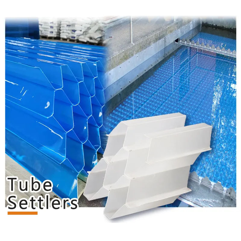
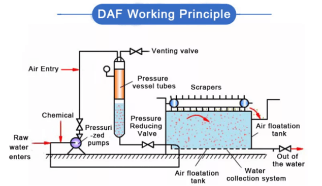
Quando le acque reflue grezze contengono concentrazioni significative di grassi, oli e grasso (FOG) o oli liberi, i sistemi di sedimentazione a gravità vanno incontro a guasti sistemici. Le particelle di olio hanno un peso specifico inferiore a quello dell'acqua e aderiscono in modo aggressivo alle superfici in plastica o acciaio inossidabile di tubi e piastre, causando incrostazioni biologiche, forti incrostazioni e gravi cortocircuiti idraulici. Pertanto, per qualsiasi flusso con concentrazioni di FOG superiori 20mg/l o contenenti fanghi colloidali a bassa densità (ad esempio, lavorazione alimentare, macelli e applicazioni petrolchimiche), DAF è la scelta del processo obbligatoria .
Al contrario, per i flussi inorganici pesanti (ad esempio, sterili minerari, lavaggio aggregati e decapaggio dell'acciaio) caratterizzati da valori TSS elevati che vanno da 500mg/l oltre 3.000mg/l , i sistemi DAF vengono rapidamente sovraccaricati. L’immenso volume di schiuma galleggiante generata sovraccarica facilmente gli schiumatoi di superficie e il volume di microbolle richiesto non può eguagliare l’enorme flusso di solidi. Questi solidi pesanti e densi sono ideali per i chiarificatori a lamelle, dove le piastre angolate ad alta resistenza e le tramogge a cono profondo facilitano il consolidamento continuo dell'addensatore a gravità e la rimozione meccanica dei fanghi.
| Parametro di prestazione | Colonizzatore del tubo | Chiarificatore lamellare | Flottazione ad aria disciolta (DAF) |
|---|---|---|---|
| Efficienza tipica di rimozione del TSS | 80% – 90% | 85% – 95% | 90% – 98% |
| Limite di torbidità dell'effluente (ottimizzato) | 2 – 5 NTU (richiede filtraggio) | 1 – 3 NTU | < 1 NTU (eccellente per colloidi leggeri) |
| Compatibilità FOG/olio libero | Scarso (incrostazioni, rischio di alghe) | Scarso (richiede una scrematura specializzata) | Eccellente (>95% rimozione diretta) |
| Resilienza al carico d'urto (solidi) | Moderato (incline alla formazione di fanghi locali) | Alto (aiutato dalla tramoggia per i fanghi a cono profondo) | Basso (richiede una regolazione immediata del riciclaggio) |
| Fattibilità della conformità statunitense (NPDES) | Stabilizza i limiti del trattamento secondario | Ideale per il pretrattamento terziario/avanzato | Massima conformità ai limiti categorici specifici del settore |
Nell’ambito del National Pollutant Discharge Elimination System (NPDES) degli Stati Uniti, gli impianti industriali e gli impianti municipali sono soggetti a rigide limitazioni numeriche sugli effluenti per TSS e parametri specifici del settore (come le linee guida sugli effluenti dell’EPA per i prodotti a base di carne e pollame). Per soddisfare i rigorosi standard di conformità terziaria riportati di seguito 10mg/l , i sistemi a gravità spesso richiedono un dimensionamento ultraconservativo e dipendono fortemente dalla sabbia o da filtri multimediali a valle. Il DAF, se abbinato a coagulazione chimica e flocculazione avanzate, può rimuovere contemporaneamente il fosforo totale (TP) fino a 0,1 - 0,3 mg/l sollevando solidi legati a bassa densità, consentendo agli impianti industriali di bypassare la complessa filtrazione multistadio e ottenere direttamente la conformità allo scarico diretto.
La progettazione ingegneristica si concentra sull'ottimizzazione delle impronte idrauliche e sulla riduzione dei costi di ingegneria civile. I progetti di sedimentazione per gravità aderiscono alla teoria della sedimentazione a bassa profondità di Hazzen, affermando che l'efficienza della chiarificazione dipende strettamente dall'area di sedimentazione ed è indipendente dalla profondità. Pertanto, l'introduzione di tubi o piastre inclinati espande la "superficie orizzontale equivalente" all'interno di un'impronta geometrica altamente compressa.
Per un chiarificatore a lamelle, l'obiettivo ingegneristico è trasformare la superficie fisica della piastra inclinata in un'effettiva area di chiarificazione orizzontale. L’equazione classica per il calcolo dell’area di sedimentazione effettiva totale è:
Dove A eff rappresenta l'area di sedimentazione effettiva totale ( mq or ft² ); N è il numero delle singole piastre; A p è la superficie di una singola piastra; θ è l'angolo di inclinazione rispetto al piano orizzontale (strettamente limitato a 55° - 60° nella pratica ingegneristica per garantire un affidabile scorrimento autopulente dei solidi); e η è il fattore di efficienza idraulica (tipicamente compreso tra 0,65 - 0,85 per compensare turbolenze in ingresso/uscita e distribuzione non uniforme del flusso).
La velocità di sfioro superficiale (SOR) o la velocità di carico idraulico (HLR) viene successivamente definita come:
Dove Q è la portata di picco di progetto. I confini operativi di queste tre tecnologie mostrano grandi differenze nella capacità di throughput:
| Metrica di progettazione | Colonizzatore del tubo | Chiarificatore lamellare | Flottazione ad aria disciolta (DAF) |
|---|---|---|---|
| Design tipico SOR/HLR | 0,5 – 1,2 gpm/ft² (1,2 – 3,0 m/h) | 0,6 – 1,5 gpm/ft² (1,5 – 3,7 m/h) | 2,5 – 6,0 gpm/ft² (6,0 – 15,0 m/ora) |
| Impronta fisica per 1.000 gpm | ~ 800 – 1.200 piedi quadrati (Bacino interno retrofittato) | ~ 300 – 500 piedi quadrati (Serbatoio modulare in acciaio autonomo) | ~ 120 – 200 piedi quadrati (Sistema compatto ad alta velocità) |
| Regime fluido (numeri di Reynolds/Froude) | Re < 500, Fr > 10⁻⁵ (Zona laminare stabile) | Re < 300, Fr > 10⁻⁴ (Flusso laminare altamente ottimizzato) | Non laminare; Micro-miscelazione turbolenta multifase |
Per le strutture esistenti sotto pressione per espandere la capacità, i sedimentatori a tubo rappresentano la soluzione di retrofit più economica . I chiarificatori tradizionali circolari o rettangolari spesso funzionano a bassi tassi di carico idraulico (0,3–0,5 gpm/ft²). I moduli fissatubi sospesi in PVC o ABS possono essere installati nelle geometrie dei bacini civili esistenti, raddoppiare o triplicare la capacità di trattamento senza aprire nuove strade. Questo aggiornamento richiede tempi di inattività minimi, in genere richiedendo solo 3-5 giorni di drenaggio del bacino per l'ancoraggio della struttura di supporto, garantendo un rischio di capitale eccezionalmente basso.
Quando non esiste alcuna infrastruttura di bacino aperto e il patrimonio immobiliare è strettamente limitato, pacchi lamellari autonomi prefabbricati or unità DAF montate su skid diventare le opzioni preferite. Funzionando a velocità idrauliche da 4 a 5 volte superiori a quelle di gravità, un sistema DAF compatto richiede circa il 20% della superficie di un chiarificatore convenzionale, adattandosi facilmente a spazi meccanici interni ristretti o in posizioni ai margini della proprietà.
Una valutazione economica completa deve guardare oltre i costi di approvvigionamento iniziali e modellare i costi del ciclo di vita (LCC) su un orizzonte operativo standard di 20 anni. Le spese operative (OPEX) determinate dal consumo di energia e dalle materie prime chimiche spesso superano i risparmi di capitale iniziali.
Il seguente modello finanziario delinea le tipiche distribuzioni di spesa per un modello normalizzato 1 MGD (milioni di galloni al giorno) capacità dell'impianto, ridimensionata per conformarsi alle pratiche standard di stima del budget AACE:
| Metrica economica | Colonizzatore del tubo | Chiarificatore lamellare | Flottazione ad aria disciolta (DAF) |
|---|---|---|---|
| CAPEX stimato (Attrezzature civili di base) | $ 150.000 – $ 300.000 (Sfruttando i bacini esistenti) | $ 350.000 – $ 650.000 (Unità autonome in acciaio inossidabile/rivestito) | $ 450.000 – $ 850.000 (Include skid integrato per la saturazione dell'aria) |
| Fabbisogno energetico specifico (kWh / 1.000 gal) | < 0,02 kWh/kgal (Raschietto a gravità o a bassa potenza) | < 0,03 kWh/kgal (Consumo energetico prossimo allo zero) | 0,15 – 0,35 kWh/kgal (Pompa e compressore a riciclo continuo) |
| Regimi di dosaggio di coagulante/flocculante | Allume: 20-50 mg/L PAM: 0,5-1,5 mg/l | Allume: 15-40 mg/L PAM: 0,5-1,0 mg/l | Allume: 30-80 mg/L (richiesta di carica elevata) PAM: 1,0-3,0 mg/l |
| Consistenza dei fanghi e oneri relativi ai costi di disidratazione | 0,5% – 1,5% DS Fango sottile e ad alto volume; elevato costo di disidratazione | 1,0% – 2,5% DS Fanghi compattati; minor carico di lavorazione meccanica | 3,0% – 5,0% DS Torta altamente concentrata; è necessario un ispessimento minimo |
Gli studi di fattibilità dovrebbero utilizzare l'analisi di sensibilità a doppio parametro per mappare i rapporti di flusso picco-medio rispetto ai picchi di solidi influenti. Se il rapporto di flusso picco-medio supera 2,0, i sistemi DAF richiedono azionamenti a frequenza variabile (VFD) sulle linee di riciclo per regolare le velocità di erogazione dell'aria. I chiarificatori a lamelle devono essere dimensionati fisicamente per i flussi istantanei di picco assoluti, il che aumenta i pesi strutturali dell'acciaio. Per gestire i costi dei prodotti chimici, gli stabilimenti possono implementare test online sui vasi e misuratori di potenziale zeta feed-forward per automatizzare il dosaggio dei polimeri, evitando il sovradosaggio di prodotti chimici e garantendo al tempo stesso una rigorosa conformità normativa.
Le prestazioni a lungo termine dei sistemi di separazione solido-liquido dipendono direttamente da rigorosi protocolli di operazioni sul campo e di manutenzione (O&M).
I sistemi a tubi e lamelle azionati per gravità richiedono un monitoraggio costante prevenire il bio-fouling e la formazione di ponti solidi localizzati . Il sedimentatore del tubo e gli array di piastre lamellari devono essere programmati per la pulizia periodica. Ogni 3-6 mesi, le vasche devono essere drenate in modo che gli operatori possano lavare i moduli con pistole a spruzzo ad alta pressione (1.000–1.200 psi, angolate esattamente parallele al passo della piastra per evitare danni alla plastica leggera). Per le installazioni esterne esposte alla luce solare, gli operatori devono dosare gli alghicidi o installare coperture che bloccano i raggi UV per evitare che una forte crescita di alghe intaschi gli effluenti.
Le operazioni DAF si basano sulla gestione delle apparecchiature meccaniche e sul controllo dei fluidi multifase. Gli operatori devono eseguire controlli giornalieri sulle pressioni di saturazione (mantenendo un intervallo compreso tra 60 e 80 psi), monitorare l'uniformità delle nuvole di microbolle, ispezionare le valvole di rilascio dell'aria per verificare la presenza di incrostazioni o ostruzioni di particolato e modulare la velocità dello skimmer. Gli schiumatoi devono bilanciare la raschiatura abbastanza veloce da evitare che la schiuma affondi con la raschiatura abbastanza lenta da evitare di mescolare l'acqua in eccesso con i fanghi. Ciò richiede operatori addestrati nei controlli di processo automatizzati e nei sistemi pneumatici.
I test standard sui vasi da laboratorio forniscono dati chimici di base utili ma non è possibile prevedere con precisione le prestazioni idrauliche su vasta scala . La progettazione di grandi sistemi industriali richiede test pilota a flusso continuo in loco. Gli impianti pilota dovrebbero essere dimensionati tra 5 e 20 gpm e funzionare per 2-4 settimane per catturare la produzione completa e i cicli di pulizia sul posto (CIP). Gli ingegneri devono dare priorità a due parametri di scale-up:
Durante i test finali di verifica delle prestazioni, gli appaltatori EPC e gli ingegneri della struttura dovrebbero valutare i sistemi rispetto a questa matrice di messa in servizio di 72 ore:
| Metrica di messa in servizio | Protocollo di monitoraggio | Criteri di superamento del sistema a gravità | Criteri di superamento del sistema DAF |
|---|---|---|---|
| Capacità di sollecitazione idraulica | Monitoraggio continuo del flusso online nell'arco delle 24 ore | Nessun allagamento del bucato al 100% del flusso di picco previsto | Funzionamento regolare del circuito di riciclo senza traboccamento di schiuma |
| Cattura dei solidi (TSS) | Campionamento composito ogni 4 ore | ≥ 85% di rimozione della massa entro i limiti di ingresso di progettazione | Rimozione della massa ≥ 92% entro i limiti dell'ingresso di progetto |
| Densità dei fanghi/schiuma | Due volte al giorno test gravimetrici di laboratorio | Concentrazione dei fanghi di sottoflusso ≥ 1,0% DS | Concentrazione di schiuma galleggiante superiore ≥ 4,0% DS |
| Conformità acustica e di potenza | Misuratore di potenza integrato e sensori dB calibrati | Assorbimento totale ≤ 105% della targa massima del motore | Livello di rumore ≤ 85 dBA a 1 metro dallo scivolo di riciclaggio |
La scelta della giusta tecnologia di separazione solido-liquido è fondamentale per evitare elevati costi di modifica futuri e garantire la conformità a lungo termine. Per assistere il vostro team nella progettazione e nel dimensionamento del processo, offriamo risorse tecniche specializzate:
Supportati da una rete di ingegneri consolidata e da inventari regionali di ricambi in tutto il Nord America, forniamo assistenza completa sui progetti, dalle revisioni iniziali della conformità agli standard dei dieci stati fino al supporto operativo a lungo termine.



86 - 571 - 88647609

+ 86-15267462807
